Background and structure of the satellite * Description of the SOYUZ-FREGAT launcher * The launch process * An overview of the geosynchronous satellite communication system
21.12.2003
From: H.L.L
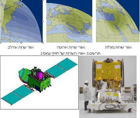
Diagram 2 (on the right) Amos 2 in a folded launch layout and on the left - Diagram 3 - the satellite in a layout configuration as it will be stabilized in space
Direct link to this page: https://www.hayadan.org.il/amos2p1.html
introduction
The Amos-2 communication satellite will be launched into space on 27.12.03 at 23:30 (Israel time) using the SOYUZ-FREGAT launcher of the French-Russian launch company STARSEM, from the BAIKONUR launch site located in Kazakhstan.
With the successful launch of the satellite, three years of activity of the Amos 2 program at the Space-Communications Company, which initiated and financed the program, will end. During this period the satellite was designed, manufactured and prepared for launch by the aerospace industry. Within a few weeks, the satellite will be placed in its approved "station" in orbit, the acceptance tests in orbit will be completed, and the Space-Communications Company will begin the commercial activity of providing broadcasting and communication services throughout the twelve years of its mission.
Amos-2 satellite program - background
The Space-Communication Company began its activity in the provision of satellite communication services in 1996 with the launch of the Amos 1 communication satellite.
The Amos 1 satellite, the product of the development and creation of the Israel Aerospace Industries, with high transmission qualities, responded to a wide variety of customers in Israel and abroad and was chosen, among other things, to serve as a platform for providing television service directly to homes by the YES company and others in Israel, and by HBO and companies More in Europe.
Space-Communication Company managed to fill the entire capacity of the Amos 1 satellite, and in view of additional demands from customers in Israel and abroad, the company decided to expand its activities and initiated the Amos 2 program. The company raised the capital required to launch the Amos 2 satellite from shareholders, banks and the capital market in Israel
In January 2001, Space-Communication ordered the Amos 2 satellite from IAA, and the program under which the satellite was created was launched. During this period, the company carried out marketing and sales activities in Israel and abroad which bore fruit, resulting in the fact that about 70% of the capacity of the Amos 2 satellite is already sold to customers in long-term contracts.
The owners of the Space-Communication Company are: Israel Aerospace Industries, Eurocom Holdings Ltd., Group H. Mr. Ltd., and GSSC Ltd., in equal parts.
Description of the satellite and its uses
The Amos 2 satellite is based on the Amos 1 platform plus improvements and innovative technological developments. The changes that were introduced were intended to meet the mission's requirements, mainly in the performance of the metad (frequency domain (KU), the number of responders, the service areas and the provider of the responders.
The Amos 2 satellite will serve customers in three service areas: Israel and the Middle East, Europe, and the US East Coast, as described in Figure 1.
The uniqueness of Amos 2 is expressed in its high power, which makes it possible to receive the broadcasts with a small receiving antenna and in excellent quality.
During its lifetime, Amos 2 will provide a wide variety of broadcasting and communication services in its service areas such as:
* Distribution of television and radio broadcasts directly to the homes of the scouts (DIRECT TO HOME)
* Distribution of television and radio broadcasts to cable centers
* Distribution of Internet services
* Data transmission to communication networks
Loaded weight 2 at the time of launch is 1370 kg and its planned lifespan is about twelve years.
The satellite has twenty-two active space segments, each with a bandwidth of 36 MHz, as well as six backup space segments.
Diagrams 2 and 3 depict the Amos 2 satellite in a launch configuration (folded) and in a deployed configuration in orbit.
Description of the SOYUZ-FREGAT launcher
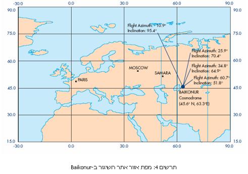
Amos 2 satellite will be launched on the Russian SOYUZ-FREGAT launcher, with the launch services provided by the French-Russian company STARSEM. The launch will be carried out from the BAIKONUR launch site in Kazakhstan, which is the main launch site of Russia (former USSR). Figure 4 shows a map of the launch site area, located at longitude 64.3? And in latitude 45.6? . The map also indicates the safety sectors (launch directions) approved from this launch site. The launch site at BAIKONUR is Russia's largest launch site and includes nine separate launch sites and over 50 launch pads.
The SOYUZ launcher is the most reliable launcher that has launched 1,683 launches since 1957, more than any other satellite launcher. The launcher has carried out all the manned launches of the Russian cosmonauts, since Yuri Gagarin until today. The launches include manned space missions in low earth orbits, as well as the transportation of the cosmonauts to the space stations, first to the MIR station, and now to the International Space Station (ISS). During this period, due to the grounding of the American space shuttle after the "Columbia" disaster, the SOYUZ pilot also launched the American astronauts to the International Space Station.
As mentioned, the SOYUZ launcher is a launcher built from three stages. With the establishment of the launch services company STARSEM, the fourth stage, the FREGAT, was opened, allowing the company to offer launch services to different orbits and to launch larger satellites.
The configuration of the launcher that will launch the Amos-2 satellite is: the three stages of SOYUZ, fourth, upper stage, FREGAT, SATELLITE ADAPTER, and FAIRING.
Figure 5 depicts the launcher.
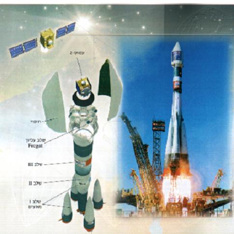
Figure 5: Description of the SOYUZ-FREGAT launcher
The main features of the launcher are:
• Total weight of the launcher at takeoff: 308 tons.
• Number of steps: 4
• Length (including the canopy): 64.5 meters.
• Diameter: 10.3 meters.
• Thrust at takeoff: 4,146 kilonewtons.
• Launcher reliability: 99.5%.
The SOYUZ-FREGAT launcher will launch the Amos-2 satellite into a geostationary transit orbit, GTO, and after its separation from the launcher, the satellite will perform several maneuvers (ABM firing), which are required for placing it in GEO. [In the appendix the reader will be able to find additional explanations for the launch process].
The launch process
21.12.2003
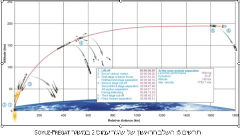
Figure 6: The first stage of Amos 2 launch on the SOYUZ-FREGAT launcher
Direct link to this page: https://www.hayadan.org.il/amos2p3.html
The process of launching an Amos-2 satellite on the SOYUZ-FREGAT launcher includes two main stages.
The first stage, which begins with the take-off stage of the SOYUZ-FREGAT, and ends at the moment of separation between the third stage of the SOYUZ from the FREGAT system to which a loaded satellite 2 is attached. This stage, schematically described in Figure 6, includes the following events:
o Igniting the four engines of the first stage, raising the launcher.
o Ending the vertical movement of the launcher.
o The ignition of the second stage, the completion of the combustion of the first stage and its disconnection from the following stages.
o Ignition of the third stage, completion of combustion of the second stage and disconnection from the third stage. removing the canopy.
o Completion of the third stage combustion.
o Separation between the third stage and the forward module (the FREGAT + Amos 2 satellite).
This stage lasts 8 minutes and about 49 seconds.
At the end of the first phase, we focus on the front module (the FREGAT + Amos 2 satellite), which weighs about 7,500 kg, is in an orbit at an altitude of 185 km, at an inclination of 51.8?, and moves at a speed of 7,750.7 meters per second.
As soon as the first phase ends, the second phase begins, the long one, schematically described in Figure 7. At the end of this phase, which consists of several events, the Amos 2 satellite will separate from the FREGAT (separation of the front module), and will be thrown into a geosynchronous transit orbit (GTO), as explained in the previous chapter.
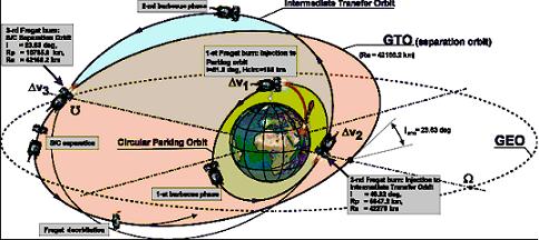
Diagram 7: The second stage in the process of launching a loaded satellite 2 by the SOYUZ-FREGAT launcher
The second stage includes the following events:
A. First activation of the FREGAT engine for 20.5 seconds (?V1 in diagram 7 in part D), and the injection of the front module into a circular parking orbit (CIRCULAR PARKING ORBIT). The route is at an altitude of 185 km above the ground and at an inclination of 51.5? (see diagram 7). The injection into orbit occurs 6 minutes and 19 seconds after launch.
B. Cruising in the parking orbit, including the rotation of the satellite using the FREGAT rotation to allow sunlight to be absorbed by the folded solar surface for the purpose of operating the satellite in this phase. (marked in diagram 7 as 1ST BARBIQUE PHASE).
third. A second activation of the FREGAT engine for about 11 minutes (?V2 in diagram 7), and the injection of the front module into a temporary transfer orbit (INTERMEDIATE TRANSFER ORBIT). The trajectory parameters are detailed in Figure 7. The injection occurs approximately one hour and 22 minutes after launch.
d. Cruising in a temporary transit orbit, including the satellite spin using the FREGAT spin similar to B, (2ND BARBIQUE PHASE)
God. A third activation of the FREGAT engine for 2 minutes and 17 seconds (?V3 in diagram 7), and the injection of the front module into a transition orbit where the satellite will be separated from the FREGAT (GTO, SEPARATION ORBIT). The orbit parameters are detailed in Figure 7. The injection occurs approximately 6 hours, 36 minutes and 47 seconds from the moment of launch.
and. Cruising in the GTO, aiming maneuvers and separating the satellite from the FREGAT. Separation occurs about 6 hours, 46 minutes and 47 seconds from launch.
G. The maneuvers of the FREGAT and placing it in a "safe" orbit as far as the satellite is concerned.
With the separation from the FREGAT, about 6 hours and 46 minutes after the launch (LIFT-OFF), the launch process ends.
The satellite starts cruising at GTO, the orbit parameters are indicated in Figure 7.
The responsibility for the satellite returns to the IAI project team.
The process of inserting and placing the satellite in the GEO-approved "station" begins, which consists of three main stages:
The first phase, which lasts about one hour and forty-three minutes from the moment the satellite is separated from the FREGAT, in which the first activities are carried out that allow the satellite to function as a system: deployment of the communication antenna, deployment of the satellite's propulsion system, deployment of the satellite's solar surfaces, solar acquisition, solar cruise, land acquisition and locking, and the first GTO track cruise.
A second phase, lasting about six days, in which the satellite's ABM is activated three times, giving the satellite a speed increase of 1,500 meters per second, and which changes the satellite's orbit from GTO to GEO.
The third stage, which lasts about ten days, in which the satellite is transported to the final station (4 degrees West in GEO).
Important notice to the readers of the science site
The site has moved to a new platform and updates continue there
This version of the science site has stopped being updated and is used as an archive only. All know-how can be accessed via the navigation bar. For those who are on the home page, we also recommend using the Google search box to search within the site (both old and new). We apologize for the inconvenience and recommend from now on to enter the new website directly. The site's main URL www.hayadan.org.il Already pointing there directly. However, the transfer of the database, which includes about 7,000 articles, will take some time, sorry.
Links to the archives: space section * the third millennium - futurism * the Israeli skeptic * nature, environment and evolution * life sciences
Hayadan
Science and space in Israel
Issue 25 of the journal Scientific American Israel was published (October-November 2006). Details by clicking on the image.
Recommended sites
Downloads
TCMAD - Young People in Science (Weizmann Institute)
The site of the umbrella organization of the disabled
The Israeli Space Association
The Astronomical Club of Tel Aviv University
Colmusant
Edge - the lists of Ami Ben Best
Big Head
track association
Israel in space
Science from a different angle
The Israeli Astronomical Society
The National Science Museum in Haifa
The Museum of Science in Israel
In the land of knowledge
A window to physics
Hamada
Science forum in Vala
The experts website
Fisher Institute for Space Research
ISRACAST
Netizen for exploring the Internet
Intelligence, military and security blog
The science expert in Israel - news | The scientist - science activities for youth Israel in space 1 - satellites Israel in space 2 - additional topics Ilan Ramon - articles about the operation Colombia disaster coverage | The investigation of the disaster - continued Articles and opinions | Yedan Amos 2 | Ofek satellites Biotechnology expert in Israel The crisis in universities Industrial research and development in Israel
Towards the launch of Amos 2 - Part D: An overview of a geosynchronous satellite communication system
21.12.2003
By: H.L.L
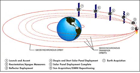
Figure 20: Schematic description of the mission of putting the satellite into GEO
Communication satellites, which are used to transmit TV broadcasts, telephony, Internet and data, are placed and operate in the geosynchronous orbit - GEOSYNCHRONOUS ORBIT (GEO). This orbit is a circular orbit around the Earth at the equator, and is about 36,000 km from the Earth's surface.
The main feature of the GEO is that every point on it is completed by the coffee every 24 hours, such as a point on the surface of the earth, therefore the point on the track appears to be "standing" towards a point on the surface of the earth. This feature allows communication services to be transferred to defined areas across the country. Diagram number 8 schematically describes the GEO.
In light of the fact that there is only one geosynchronous orbit orbiting the Earth, it is managed by the International Telecommunication Union (ITU) which creates a framework for carrying out satellite frequency coordination processes between different satellite networks in order to prevent mutual interference.
Each GEO satellite communication system consists of three main segments:
Space segment: the satellite (or satellites) moving in GEO and operating the communication mast for the provision of communication services.
Ground segment: A ground control center that operates the satellite, or satellites, during their lifetime in orbit.
The user segments: the networks of the satellite communication service providers who operate the communication networks for the use of their customers.
In addition to these three sections, the following elements required to operate the system must be included:
- Launching the satellite from the surface of the country and placing it in the geosynchronous orbit at the approved point ("station").
- Insurance of the system for the entire duration of the mission for the purpose of securing the realization of the business plan.
- Coordinating the satellite frequencies, as part of the ITU coordination processes for its registration and approval of its operation on the "station".
The satellite network, defined by the GEO operated satellite and the ground user segment, is the one that enables the provision of communication services. The network includes three main elements:
- The "up-link station" for the satellite (UP-LINK STATION), such as a broadcast station of a TV channel, which transmits the signals to the satellite. These stations are located in the service areas (SERVICE AREAS) created by the satellite.
- The satellite itself, which is located in GEO, and receives the incoming signals through its communication mast, which consists of a receiving antenna, the transponder system, and a transmitting antenna. The received signals are amplified by the transponder, change the frequency, are amplified, and are transmitted back to earth via the satellite's transmission antenna, to the defined service areas.
- The receiving station or the "DOWN-LINK STATION", located in the service areas of the satellite, receives the signals transmitted from the satellite, decodes them and displays them on the user's home television screen. An example of a receiving station is the YES antenna + the YES converter.
Diagram 10 schematically describes the satellite network, and diagram 11 schematically describes the satellite's service areas.
The GEO satellite communication system makes it possible to provide communication services from one point to a large number of points included within the satellite's service areas (POINT TO MULTI-POINTS COMMUNICATION SYSTEM), where all points receive communication services with guaranteed minimum qualities.
The main services of the GEO satellite communication system are TV and data transmissions. The television broadcasts, most of them all, are digital compressed broadcasts (DIGITAL COMPRESSED BROADCASTING), which allow direct reception in the viewers' homes (DIRECT TO HOME - DTH). Most satellite channels today are broadcast as DBS (DIRECT BROADCASTING SERVICES).
The diagram shows the satellite in GEO receiving the channel packages transmitted to it from the transmission station (UPLINK STATION). The broadcasts are broadcast from the satellite and received in the consumers' homes using small home receiving antennas (diameter of 60 cm to 1 meter). The signals are received in the converter (IRD) which also includes a "smart card" that allows the subscriber to be identified, the compressed signals to be decoded and displayed on the television set, or on the home computer, and if the signals are audio signals - to be broadcast through home audio systems. The smart card makes it possible to make the monthly charges of the subscriber, to allow him to order additional channels, paid movies, etc.
Most data communication is carried out using VSAT (VERY SMALL APERTURE TERMINALS) networks. These networks make it possible to connect branches of the same business (for example: bank branches, supermarkets of a certain chain, pharmacies, etc.). The system consists of a central station (HUB STATION) that connects the satellite and the end stations of the system. Using the network you can connect any two end stations directly or through the HUB. Figure 13 schematically describes a VSAT network, and Figure 14 describes the VSAT equipment at an end station.
Using VSAT networks, it is possible to link remote areas (REMOTE AREAS), which are not connected to the terrestrial communication lines, to main telephone exchanges via satellite. It is also possible to deploy SCADA (Supervisory Control And Data Acquisition) networks for monitoring and receiving various data, as well as Internet connectivity. Figures 15, 16, and 17 describe these uses.
A geostationary communication satellite, through which the various communication networks reviewed earlier are activated, consists of a satellite platform ("BUS") and a communication payload (COMMUNICATION PAYLOAD).
The communication hub is the "payload" of the satellite, and through it the satellite communication services are provided. It consists of receiving and transmitting antennas and the transponder system. In most cases, the MET also includes the transmission and reception components of the satellite's command and telemetry system.
The purpose of the satellite platform is to "hold" the communications mast in orbit, to provide it with the required electrical power, to keep the antennas pointed at the defined service areas, and to protect the system from the environmental conditions during the launch and in orbit. The satellite platform consists of the six subsystems as described in the diagram.
With the completion of the satellite development process, all airborne units are manufactured. The units are assembled on the satellite structure (STRUCTURE), undergo testing and integration processes. Upon completion of the satellite assembly, it undergoes integration processes, tests, environmental experiments (simulation of launch conditions and track conditions), and at the end there is an initial acceptance survey of the satellite, which allows it to be transported to the launch site. At the launch site, activities are carried out to prepare the satellite for launch, including its installation in the launcher. The satellite is integrated into the launcher in a launch configuration: the solar surfaces are folded, the communication antennas are folded, the power supply is made through the battery and only to the units whose operation is required during the launch (this is in order to save electric power limited by the battery).
The satellite is launched from a designated launch site of the selected launcher. The launchers currently available on the market are of the expendable launcher type (EXTENDABLE LAUNCH VEHICLE), based on the intercontinental ballistic missile technologies that were developed in the 1960s, and converted to launch satellites.
Launching satellites into geostationary orbit is carried out in two stages:
o The first, using the launcher, is the injection of the satellite into a geostationary transfer orbit (GEOSTATIONARY TRANSFER ORBIT - GTO).
o The second, by the satellite itself, beyond the geostationary orbit (GEO) and placing it in the approved "station".
The GTO is an elliptical orbit (Figure 19), with an apogee (the apex of the ellipse far from the Earth) of GEO (that is, 36,000 km), and a perigee (the apex of the ellipse closest to the Earth) of 300-4,000 km, and an inclination (the angle between the GTO plane and the Earth's equatorial plane) of 7-25°. These parameters depend on the location of the launch site (the latitude of its location).
The GTO features are characterized by the launcher: its lifting capacity, launch site location, and more. The smaller the inclination of the GTO plane, and the higher the freegia of the GTO, the less fuel is required for the GTO maneuvers. The smaller the amount of fuel, the more it is possible to extend the life of the satellite mission, and/or increase the number of active responders it carries.
The launch sites closer to the equator are more attractive for GEO launches than the sites further from it (the inclination of the GTO plane is smaller). Therefore, the launch service companies that provide launches using launchers launched from northern sites (such as BAIKONUR) are required to inject the launched satellite into such a GTO that allows the satellite to perform maneuvers (ABM firing) for entering the GEO at the same velocity increment (DV) required from a GTO of Launchers (such as ARIANE launchers) launched from the launch site in KOUROU, FRENCH GUIANA, located at latitude 7° north of the equator.
As mentioned, the satellite is injected by the launcher into the GTO, and after the separation between the satellite and the launcher, the process of insertion into the geostationary orbit is carried out, which lasts about ten days and consists of the following three stages:
A. First step: performing the first operations that allow the satellite to function as a system: purchasing land, deploying solar surfaces and disconnecting the battery from the electricity supply system, deploying communication antennas, activating all the satellite systems, continuing cruising in the GTO.
B. Step two: Login to GEO. The process requires "rounding" the GTO (elliptical orbit) into a circle with a radius of 42,000 km from the center of the country (36,000 km from the surface of the country), while canceling the inclination of the GTO plane, that is: achieving an inclination of 0°. These actions are achieved by giving the satellite a speed boost when it is at the apogee of the orbit. The total speed increment required is DV 1,500 M/SEC. The additional speed is given to the satellite by activating the satellite's large engine (APOGEE BOOST MOTOR - ABM) in three sessions for a cumulative time of about one hour. The thrust vector of the engine is designed so that while giving the satellite the additional speed it will also cause the inclination to be reduced to .0°
third. Third step: When the satellite is inserted into the GEO, it is placed in a "station" in a confirmed manner while drifting in orbit, from the point where it was inserted to the "station". Diagram 20 at the top of the article schematically describes the stages of the process.
The last step before the delivery of the satellite to the customer is the stage of the final acceptance tests in orbit (IOT), in which the satellite manufacturer proves to the customer that all the guaranteed performances of the satellite system are achieved in orbit.
