The TECSAR radar satellite, which sends outstanding photographs of its kind, is an expression of the ability of the industry in Israel - and especially the aerospace industry - to design, manufacture satellites and launch them into space
Uri Naftali Galileo Magazine
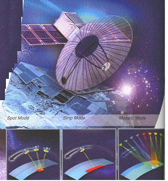
On January 21, 2008, Israel's first SAR (Synthetic Aperture Radar) satellite - TECSAR - was launched from India. The name TECSAR is derived from the combination Technology SAR Satellite, and indicates the purpose of the radar - demonstrating satellite SAR technology. This technology makes it possible to produce from the radar an image of the photographed area day and night, in all weather conditions and in all visibility conditions. The successful launch of the satellite and the excellent photographs it provides released a sigh of relief from everyone involved in its development. Here we will focus on the impressive technological achievement, which is expressed in the ability of the industry in Israel - and in particular the aerospace industry - to design, manufacture satellites (especially radar satellites) and launch them into space. We note that the development program started from scratch, without any previous experience with SAR satellites.
First class performance
Only nine countries belong to the club of countries that have perfect space capability (development, production and launch), and these are (according to the chronological order of the launch of the first satellite): the Soviet Union (and today: Russia), the United States, France, Australia (which is not currently active ), Japan, China, Britain (which launched but did not continue this activity), India and Israel (and since the publication of the Galileo article about two months ago, Iran as well). The number of countries with the production capacity of radar satellites is even more limited: the United States, Russia, Germany, Canada, Japan, Italy and Israel.
The MBT plant of the Aerospace Industry was chosen in the eighties of the last century to lead the space projects of the State of Israel. Since then, the plant has gained a lot of experience in the field of building, launching and operating satellites of various types: electro-optical observation satellites, communication satellites, and now radar satellites. The satellites produced by the Israeli industry excel in their light weight, which results from the limitations of launching from Israel, and first-rate performance, which results from Israel's special needs. Mbat plant is the main contractor of the TECSAR satellite. Alta Systems - a subsidiary of the Aerospace Industry - developed and manufactured the radar of the TECSAR satellite. The development of SAR radars began at Elta about 25 years ago, and today Elta manufactures and assembles SAR radars for a variety of aircraft: fighter jets, executive jets, light aircraft and even UAVs (unmanned aerial vehicles). Therefore, she was chosen to lead the development of the radar for the space system.
SAR satellite - for nothing?
For several years, Israel has had the ability to receive optical images from space, but optical satellites such as Eros, Ofek, SPOT, Landsat, Ikonos and similar satellites cannot take pictures in poor visibility conditions, such as night, cloudy , fog, sand and dust storms. These restrictions greatly reduce the efficiency of the electro-optical satellites. Therefore, these satellites are almost useless in those regions of the Earth that are covered by fairly constant clouds. In contrast, the sensor in the radar satellite "brings the sun with it", that is, it actively "illuminates" the surface, and thanks to the relatively long wavelength it uses, this satellite is able to provide images even when other systems fail. The radar sensor transmits electromagnetic radiation, so it is particularly sensitive to metallic objects that reflect this radiation strongly. That's why radar can detect large man-made objects, such as airplanes, vehicles, trains and ships. In this way, it is possible to locate wreckage of crashed planes or ships in distress, and assist in rescue efforts. The radar transmits a controlled signal, thus avoiding dependence on natural light sources, which have no control over the signal received from them. From the data of the transmitted signal it is possible to obtain very fine information about the photographed area.
SAR radar
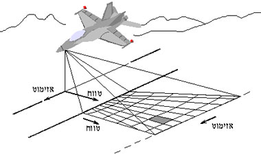
The purpose of the SAR radar is to produce an image of the photographed surface. To get a clear picture, you have to get as good a resolution (resolution) as possible, on the order of meters. However, the radar simply has a rather poor resolution both in the range direction and in the azimuth direction (the range direction is the direction in which the waves transmitted from the radar move to the target, while the azimuth direction is in the direction of the radar's movement, see picture 2). SAR systems are designed to "force" the radar to produce good separation capability in range and azimuth. We use different techniques in order to improve the resolutions of the two image axes: a good resolution in the range is achieved by using a technique called "pulse compression", which we will explain later. In the azimuth direction, the resolution can be improved by transmitting from a very long virtual "antenna", hence the name Synthetic Aperture Radar, i.e. synthetic aperture radar.

The technique of improving the separation in the direction of the range in a normal radar, which transmits energy in pulses, the duration of the pulse determines the resolution, therefore the resulting resolution may be in the range of hundreds of meters and even kilometers. In airborne systems, it is possible to distinguish planes even at these resolutions, since they are individual targets. On the other hand, it is clear that with these resolutions it is not possible to obtain clear images of the ground surface. In order to get a resolution of 1.5 m in a normal radar, for example, a pulse must be transmitted for a duration of ten nanoseconds (ns). Such short pulses transmit very low energy, which will significantly impair the radar's performance. Therefore, a way is required to transmit a long pulse, but still get the desired resolution in the range direction. The method that enables this is called "pulse compression". In this method, the transmission frequency changes during the pulse. When the frequency changes linearly, the signal is called LFM Linear Frequency Modulation), see the next picture). Thanks to the frequency change, a sort of "marking" is created within the pulse, so it is possible to separate the different parts of the pulse and associate them with different targets, even if these targets are closer to each other than the basic resolution (without "pulse compression"). If so, the pulse compression breaks the connection between the resolution and the length of the pulse and makes the resolution dependent on the change of frequency during the transmission of the pulse (the width of the film) only. Since in the existing technology the width of the transmitted film can reach tens and hundreds of megahertz, the resolution of the compressed signal can be of the order of a few meters or even less. Therefore, the pulse compression method is used in all SAR radars to improve the resolution in the direction of the range (the line connecting the radar and the target). However, this method is used in other types of radar to improve resolution in the range direction. The uniqueness of the SAR radar is in performing signal compression in the azimuth direction as well, a capability that we will explain immediately.
Improving the ability to separate in azimuth
In a normal radar, the resolution in azimuth is determined by the size of the radar beam in space, and usually this is a resolution of the order of kilometers. Since a wide antenna produces a narrow beam, and vice versa, apparently all we have to do to improve the resolution is to increase the width of the transmitting antenna, thereby reducing the size of the beam. However, it is obvious that it is impossible to increase the antenna to more than a few meters or a few tens of meters at most; Moreover, to obtain a resolution of a few meters requires an antenna hundreds of meters or even kilometers long. To get such a long antenna we make a synthetic antenna (hence the name: synthetic key radar). That is, thousands of pulses are transmitted from a relatively small antenna during a certain time. During this time the radar moves and thus a very long synthetic antenna is actually created, with the length required to obtain the requested photo resolution. The ability to create the synthetic antenna lies in the ability to utilize slight frequency deviations, caused by the movement of the radar. These distractions are due to the Doppler effect (see below): as we know, the frequency of the siren of a moving vehicle is higher when the vehicle moves towards us and decreases as it moves away; This change of frequency is known as the Doppler effect. This phenomenon also exists in electromagnetic radiation, including radar waves. To create the Doppler shifts, SAR radars must be in motion relative to the imaged target. Each point in the "illuminated" (projected) area of the radar beam returns the transmission at the shifted frequency with a characteristic Doppler shift, where the shift depends on the change in the relative speed (as a vector magnitude) between the point being tested and the radar. In other words, from each point in the photographed area we get a Doppler deviation that varies according to the position of the radar in relation to the target (photo 4).
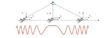
It can be shown that at small angles, the Doppler frequency of each point illuminated by the radar beam changes linearly during the movement of the radar: but this is exactly the same type of frequency change created in order to improve the resolution in the range! But in the range axis the frequency change is created by the frequency change during the transmitted pulse, and in contrast, in the azimuth direction the relative movement between the radar and the target is what creates the frequency change. Since the shape of the resulting signal is similar, the same methods that allow the resolution improvement in range are used to improve the resolution in azimuth. However, we must remember that the Doppler reflection from each target does not arrive separately, but all at once from the entire area illuminated by the beam, so we must separate the different reflections. It is possible to know exactly the expected return frequency from knowing the location of the radar and the target at any moment, and from this to filter out the frequencies that do not match the expected frequency (unlike a normal radar, targets are not searched for in a SAR radar - the location of the targets is known in advance; the magnitude of the return is the missing). As is the case in the range direction, the image resolution in the azimuth direction is determined by the tape width of the linearly variable frequency signal, the LFM. The resolution in azimuth is inversely dependent on the shooting time. Therefore, all we have to do to improve the resolution in azimuth, is to shoot at a longer time, that is, create a longer synthetic antenna. Shooting times of a few seconds will result in a resolution of a few meters. Doppler effect on the tip of the fork Doppler effect causes the wavelength of waves to shift when the source moves relative to the observer. If the range to the target and back is , then the phase accumulated by the electromagnetic wave during the journey is:

If there is a relative movement in the perpendicular direction of the radar with respect to the target, then this phase changes. The rate of phase change defines the frequency, therefore the movement causes a change in the appearance of frequency of:

And this is defined as the Doppler frequency.
Useful SAR
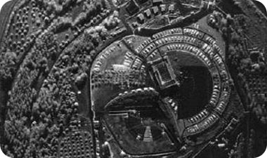
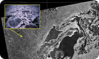
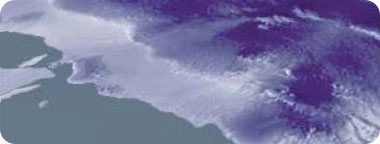
The great advantages of SAR photography have begun to be tested and manifested in recent years, and more sophisticated methods are now used to process SAR images. Ostensibly, this is advanced photography that allows you to work in any lighting conditions, but still - it's just photography. However, the control of the transmitted wave and the possibility of knowing exactly what is being transmitted at any given moment, make it possible to obtain much more data on the photographed area. SAR images are also used to monitor the polar ice caps during periods when darkness prevents other sensors from transmitting data, the very act of receiving the image is important for many uses. For example, continuous monitoring of oil slicks that are clearly visible in the SAR image, or monitoring of glaciers even at night (photo 5). Indeed, SAR images are used to monitor the polar ice caps during periods when darkness prevents other sensors from transmitting data (Figure 6).
The TECSAR radar
The requirements for the TECSAR satellite - resolution, coverage, weight and maneuverability - are extremely high, and the TECSAR radar, which was developed to meet them, excels in its low weight and excellent performance. SAR satellites have always been considered heavy satellites, due to the need for a high power electrical system. The weight of other SAR satellites in the world reaches several tons and even over ten tons. And here the TECSAR was designed in advance using materials and methods designed to greatly reduce the weight to only 300 kg. The low weight of the satellite, as well as its low moment of persistence, give great agility in its operation and in performing maneuvers, which heavy satellites cannot perform. In order to get a radar with such a low weight, careful planning was carried out for the weight of the various components. So, for example, the reflecting surface of the antenna is made of a mesh, and not a solid surface. This net weighs very little and we were able to develop such a net that does not harm the radar's performance. Despite its lower weight than similar satellites in the world, the satellite's performance does not fall - and even surpass - the performance of other systems. To get this performance, the satellite is able to take pictures in several modes of operation:
- Scanning mode (Strip mode)
- Spot mode
- Wide coverage mode
- Mosaic mode
In scanning mode (photo 7), the satellite does not perform any maneuvers and photographs the strip on which the antenna's illumination spot is pointing. Since this mode is simple to perform, it was used in all the first radar satellites and is a mode of operation that exists in every SAR system satellite even today. However, in this mode of operation the resolution in azimuth is limited to half the physical length of the antenna. This length cannot be significantly shortened, because then the antenna gain will decrease and the signal coming back from the ground will be too weak. The low weight of the satellite, as well as its low moment of persistence, provide great agility in its operation and in performing maneuvers that heavy satellites cannot perform. In order to overcome this limitation and reach improved resolutions, the antenna beam must be suspended for a longer time over the photography area. This operation is performed in a focusing manner (Spot, photo 9), which utilizes the mechanical scanning capability of the satellite. In action, a maneuver is performed so that the radar beam illuminates the photo area for a longer time. From here we can extend the shooting time and therefore improve the shooting resolution. Although, in the focusing method, the resolution is improved, but the requirement to "freeze" the beam on the ground results in covering a rather small area.


In order to benefit from the advantages of the wide coverage without compromising the resolution, the mosaic method was developed at Alta (in collaboration with MBT personnel, among whom I would especially mention the late Dr. Amir Klein). In this mode of operation, the mechanical scanning ability of the satellite, which inhibits (but does not stop) the spot on the ground, and the electronic scanning ability of the radar, which enables the beam to bounce, is reflected. This way we can get a wide coverage with improved resolution (image 10). As mentioned, the mosaic mode does not exist in any other SAR satellite, and it is currently impossible to realize it in the other satellites; This is because only the TECSAR satellite combines the ability of electronic and mechanical scanning at the same time.


In conclusion, the development of the TECSAR satellite is an achievement on a global scale. To enable the reception of images in any lighting or weather conditions, the satellite uses a radar payload (dedicated payload) for the ground photographs. The technique of using radar to obtain an image is called SAR - Synthetic Aperture Radar. This technique requires the detection of tiny Doppler shifts to create a very long synthetic antenna. The good resolution obtained in the SAR images is due to the compression of the transmission pulse on the one hand and the compression of the Doppler signal on the other. The modular design of the TECSAR radar and the light weight of the chassis allow the design of satellites derived from this satellite, and they are suitable for a variety of tasks. Thus, for example, it would be possible to further reduce the weight of the satellite and adapt it to a planetary mission to the Moon, Jupiter or Venus. The success of the first TECSAR satellite gives a great boost to the development of additional SAR satellites made in Israel. In memory of my friend and brother Dr. Amir Klein (2008-1949) Acknowledgments Thanks to Dr. Eli Yadin from "Alta Systems" who read the draft of the article and made his helpful comments. Dr. Uri Naftali is a researcher and developer in the field of space systems, visual intelligence and radar enterprise, Elta Systems Ltd. Dr. Naftali accompanies the TECSAR project from the beginning. From: Galileo Magazine

2 תגובות
Fascinating article, a lot of technical and physical terms but really interesting to read!!
(Even if you don't understand everything 100% to the end....)
Very interesting, and indeed a national pride, the question is whether the officials in charge of this system also know how to utilize it properly and translate its technological capabilities into actions on the ground. For example, maybe some attack on Iran, maybe destroying all their missile launch facilities....